
From the electric truck to the grid

From
Christian Vögtli
5 March 2026
From an evaluation project for e-trucks by a partner company, eight large traction batteries with a nominal capacity of 560 kWh were recovered for a second life. The application area of these batteries is very limited, which makes them unattractive for smaller applications, especially as they were only functional when connected as a cluster of 4 batteries. Therefore, it was decided that a large storage system should be created as a showcase that can stabilize the Swiss power grid.
The grid stabilization with a second-life battery storage serves the integration of renewable energies and conserves resources in material usage.
Within just one year - from planning designs to the qualified operational start in the balancing energy market - exciting steps were taken that demonstrated the agility and expertise of Modual AG.
Since February 2026, the system with a usable capacity of approximately 500 kWh and an approved grid power of 345 kW has been in operation for Swissgrid with 100% reliability.
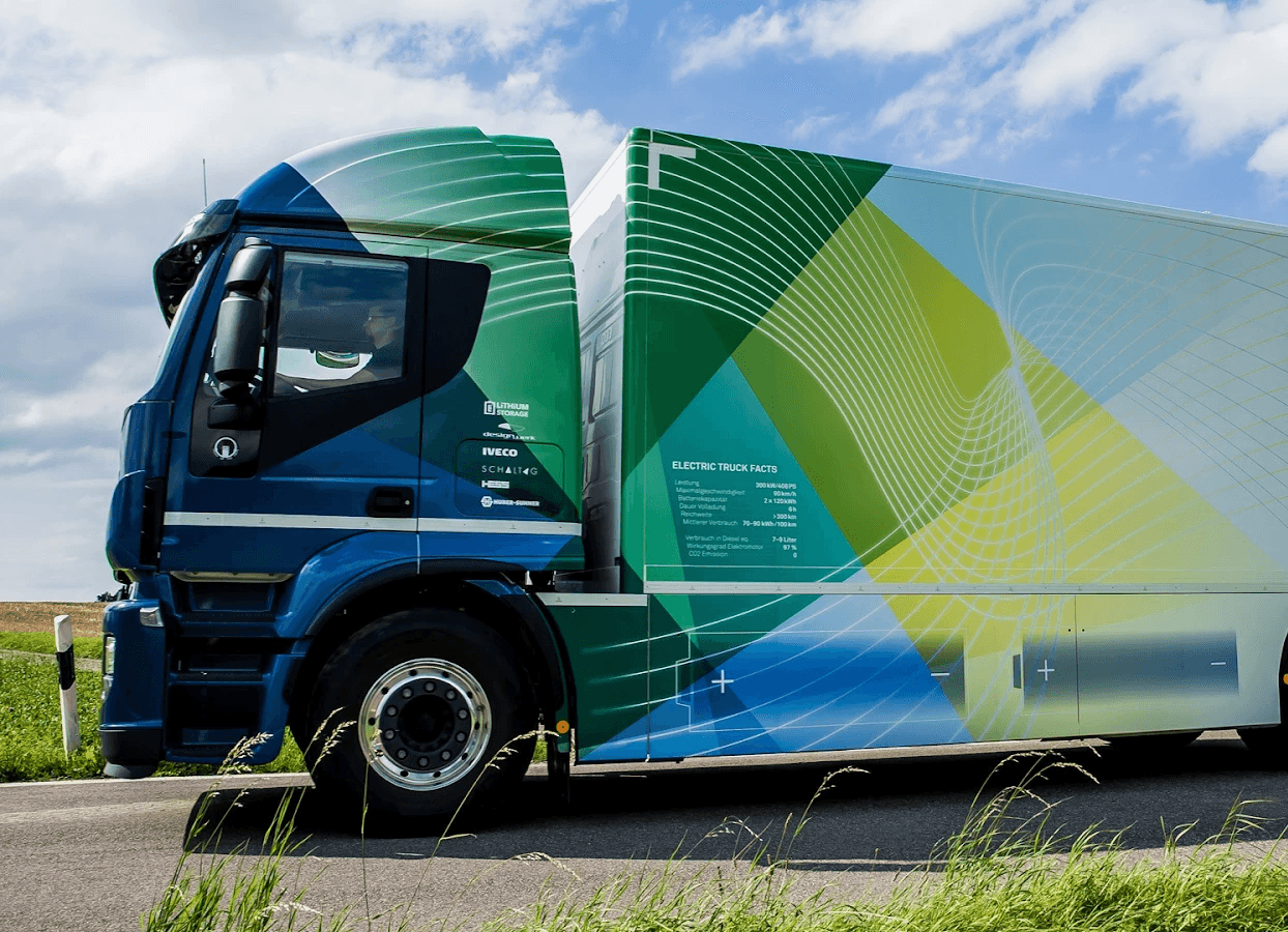
Figure 1. Electric truck (eforce, 2026)
After testing the batteries, then the site selection
Once their future application area was clearly defined, the batteries were carefully tested again after their long dormant phase. The battery condition - a critical factor in the selection of second-life batteries - turned out to be exceptionally good. Previously, they had only been used in test operations before awaiting their next use in a deep sleep for several years.
In February 2025, planning began with site selection, requests for grid and connection conditions, rental and usage contracts, building permits, as well as the rough planning of the technical setup.
Even the site gives its building a second life
The site selected was a small technical room measuring 4.5 x 2.5 m of a former mining project, which is conveniently connected with a sufficient grid connection with a medium voltage transformer nearby. This initial situation often proves critical for the economic success of many such large storage projects. Expanding or even developing a new grid connection can cause considerable delays and costs.
Power electronics as the key to grid coupling
In the evaluation of suitable battery inverters for powerful grid connection, initially different, modern photovoltaic hybrid inverters were selected and tested with a battery cluster. The configuration of several such devices on a DC intermediate circuit is (still) not a common use case for these devices, and so no reliable operation could be guaranteed.
For the battery inverter, a suitable product was found with an already known supplier. We relied on a water-cooled, rack-mounted inverter module to effectively dissipate the loss of up to 15 kW in the given, very small space to the outside. These modules were also extensively tested with a battery network before the planning of the inverter rack was finalized.
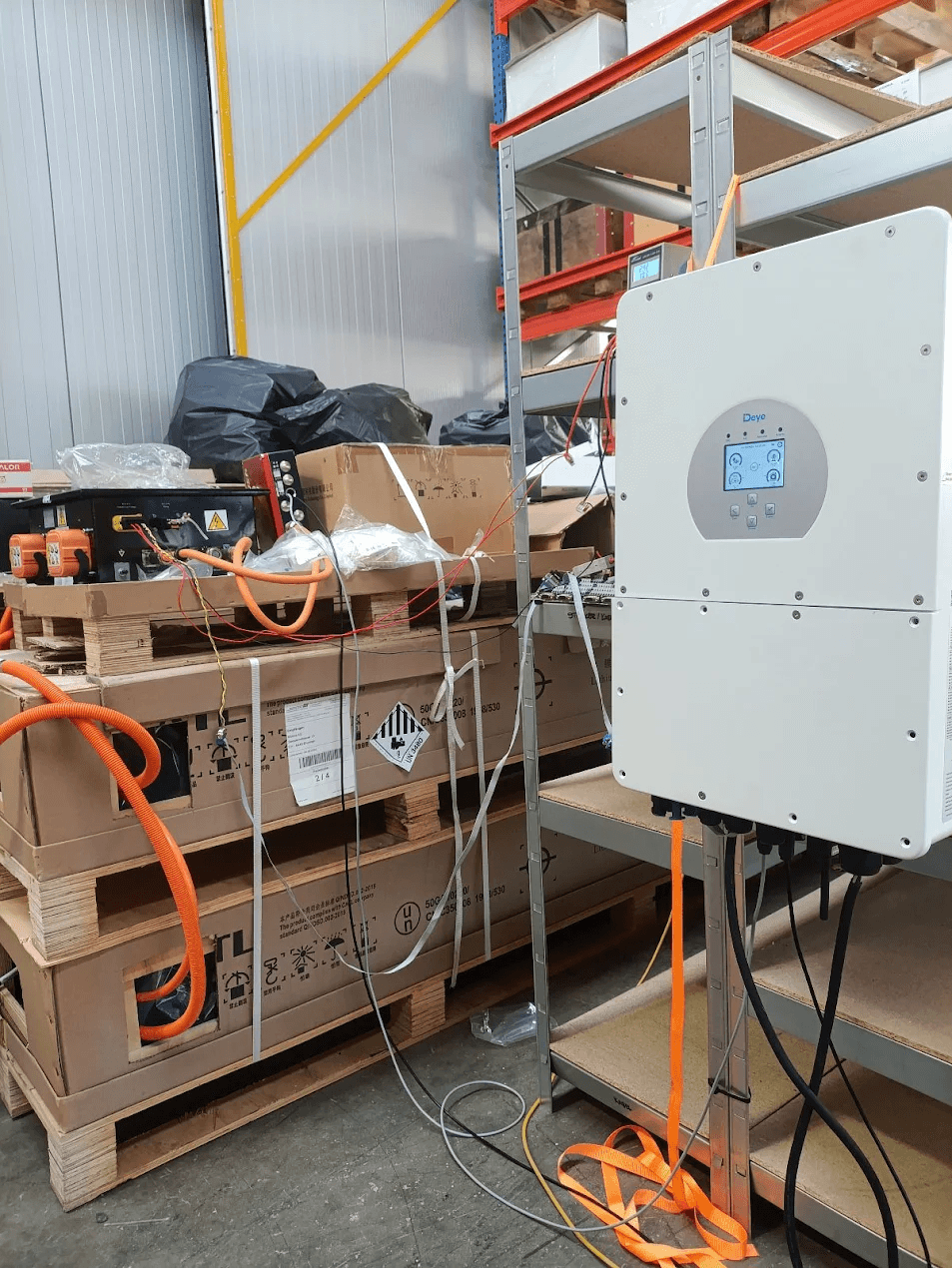
Figure 2. A Deye hybrid inverter in test operation with the truck batteries.
An additionally attractive effect of water-cooled power electronics is their high power density. In a server rack with only a base area of 80 cm x 160 cm, 12 inverter modules with a total output of 420 kW including PLC control for the entire system, circulation pump, and other fittings were easily accommodated. The water-air cooler necessary for the cooling circuit is mounted outside the building and allows the operation of the system at maximum performance in continuous operation even at summer temperatures.
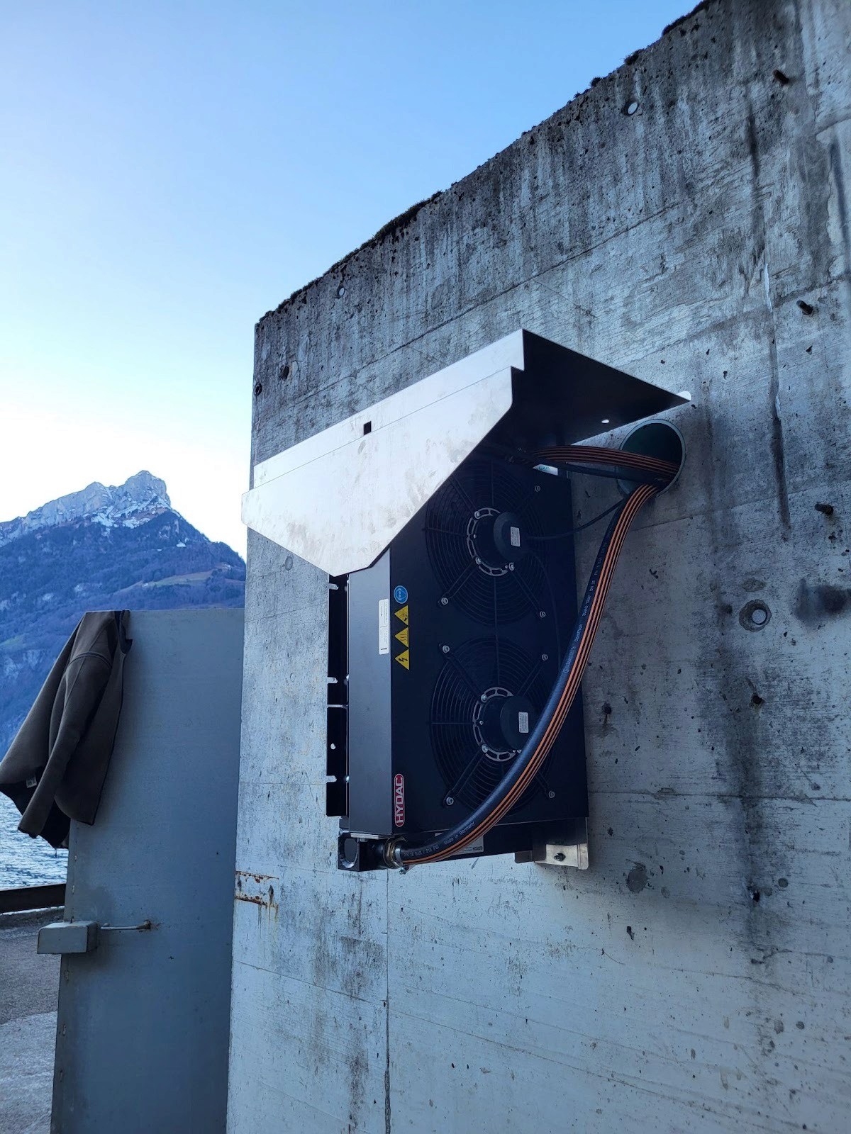
Figure 3. Water-air cooler outside the building.
How the battery giants found their place
The insertion of the 450 kg batteries was carried out with muscle power and lifting equipment - heavy machinery could not have been transported to the installation site. The batteries will spend the next 15 to 20 years on a standard heavy-duty rack - thermally well cared for by a temperature management system that can both heat and cool the batteries via the separate water circuit.
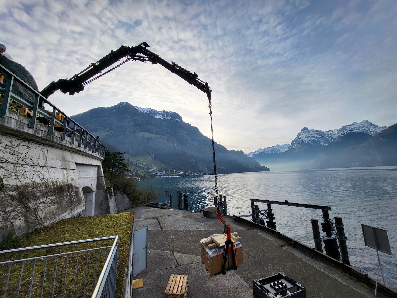
Figure 4. Crane placing the heavy batteries and power electronics at the site.
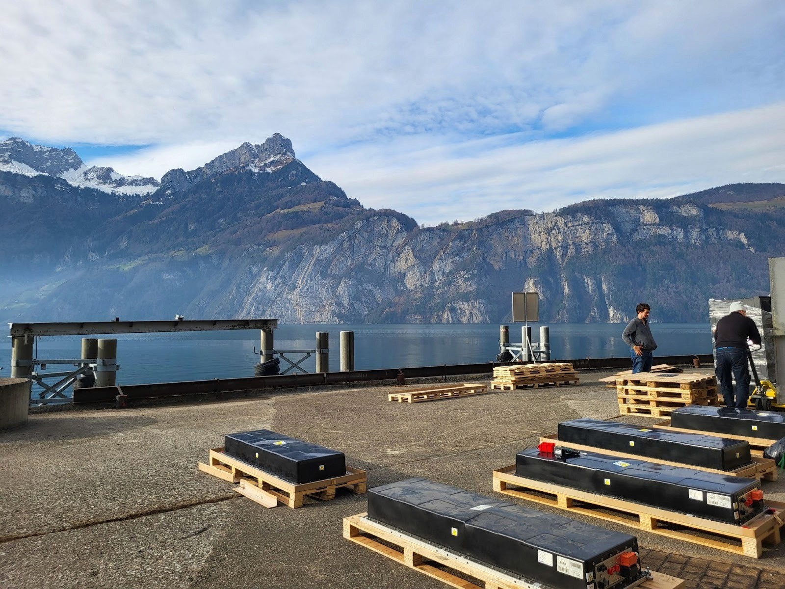
Figure 5. Batteries before the deployment site.
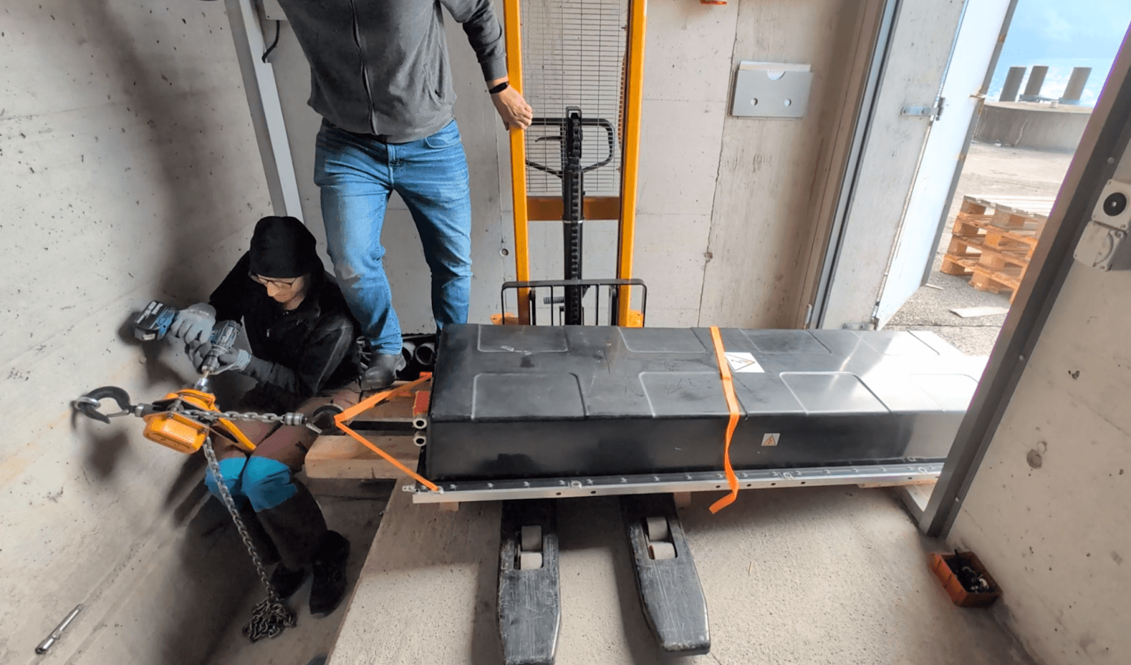
Figure 6. The installation of the batteries was carried out by manual manipulation aside from crane loading.
Step-by-step commissioning
After the grid connection between the existing transformer and the newly installed electric table was laid and checked in mid-January 2026, the system went live on January 19, 2026. Cooling circuits were filled, tests were run, parameters adjusted, and everything prepared for the prequalification test with the balancing pool service provider and Swissgrid. This so-called “prequalification” serves to validate for the operators and managers of balancing energy pools that the system behaves correctly and can be controlled reliably and without delays from afar.
The test took place at the beginning of February and so the system could transition to the qualified balancing energy market without further objections as of February 16, 2026.
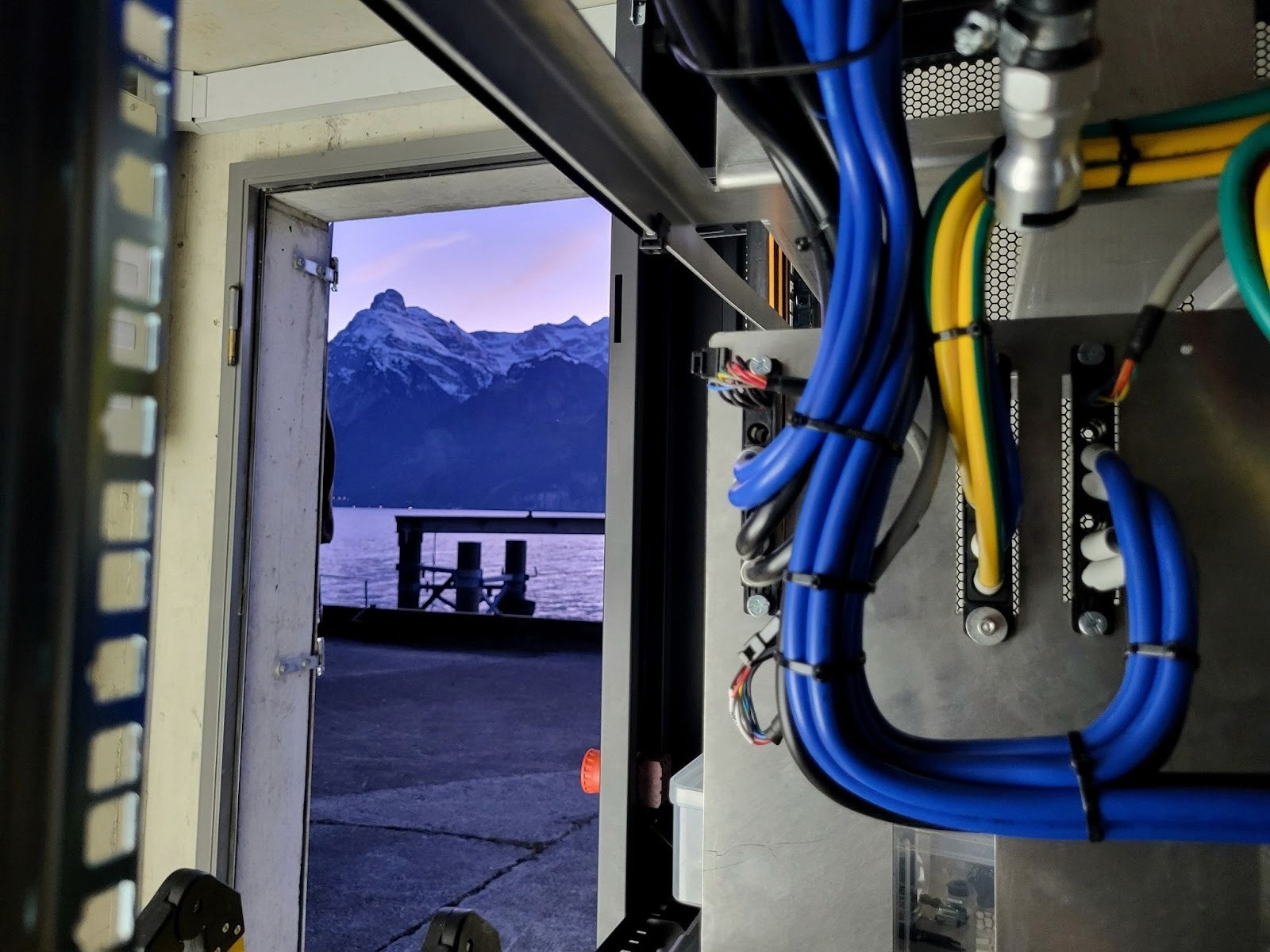
Figure 7. Insight with lake view: Detail with cabling of the power modules.
Task and payment of the battery system in the power grid
Balancing power ensures that power generation and consumption in the national and international power grid are always balanced so that the grid frequency remains stable. If necessary, the transmission system operator initiates short-term power adjustments at flexible power plants, storage facilities, or consumers. They offer their available power through central auctions where the required balancing power is procured.
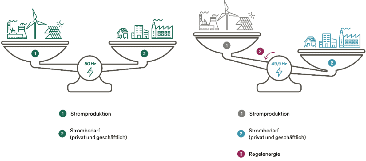
Figure 8. Illustration of the balancing energy market (Primeo Energie, 2026)
Battery storage opens up entirely new possibilities compared to conventional power plant capacities. They can not only feed energy into the grid for a short period (positive balancing energy) but also absorb surplus energy (negative balancing energy) - and this with very short reaction times and high efficiencies compared to pumped storage power plants.
In terms of capacity, however, batteries are significantly smaller than the historically central large power plants. So that Swissgrid does not have to deal with numerous small systems, there are so-called poolers who take over the administrative effort and control on the last mile for a defined margin, enabling small capacities to participate in the balancing energy market. In the facility shown here, we work together with Primeo Energie.
A storage in such a deployment can achieve a revenue of approximately CHF 70,000/MW per year (2024 & 2025); in 2022 & 2023, the payments were even 5 times higher. This allows such investments to pay off within a few years - especially if the conditions regarding location and grid connection are already met in advance.
Additional investment security can be achieved by linking several usage models such as peak load capping or self-consumption optimization of neighboring properties. The power reserve (kW) is interesting for the balancing energy market, and the energy reserve (kWh) for self-consumption optimization or arbitrage.
Technical Specifications
The installed battery storage system is technically comprised of two identical subsystems each consisting of a second-life battery cluster, comprising 4 water-cooled high-voltage traction batteries with a total capacity of 560 kWh (nominal) and 6 associated AC-DC converters.
A subsystem has a capacity of 280 kWh at a nominal voltage of 650 VDC.
The batteries are stored on two heavy-duty racks placed one behind the other, located in the back part of the room.
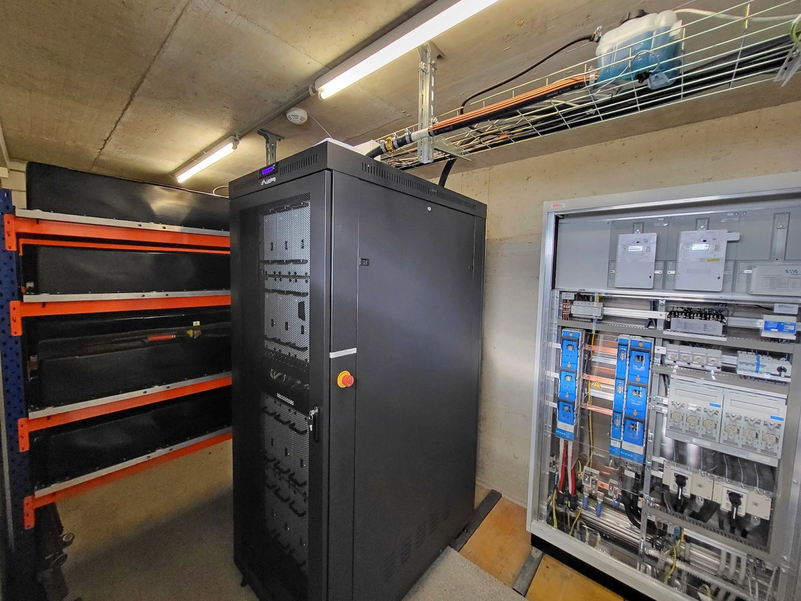
Figure 9. From left to right: Battery rack, power electronics cabinet, and electric panel with meter.
The inverters are built in a rack together with the main control and other components for their water cooling. They have a peak power of 12 × 35 kW, or 420 kW. The system power is limited to 345 kW in regular operation due to the grid connection.
The electric panel with the energy meters and main fuses, as well as main switches, is attached to the wall on the right and forms the link between the battery system and the adjacent grid transformer.
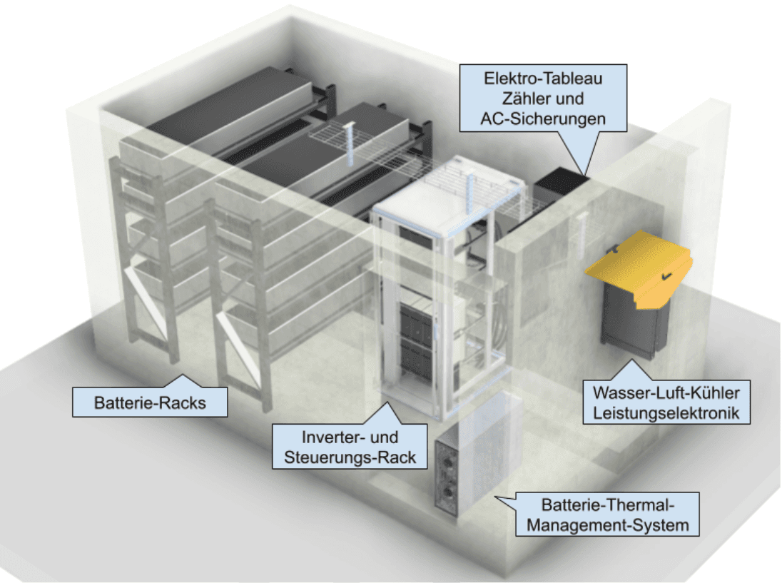
Figure 10. Illustration of the large battery system at the deployment site.
Do you have questions about this battery storage system or can we advise you on a new system? Contact us today.